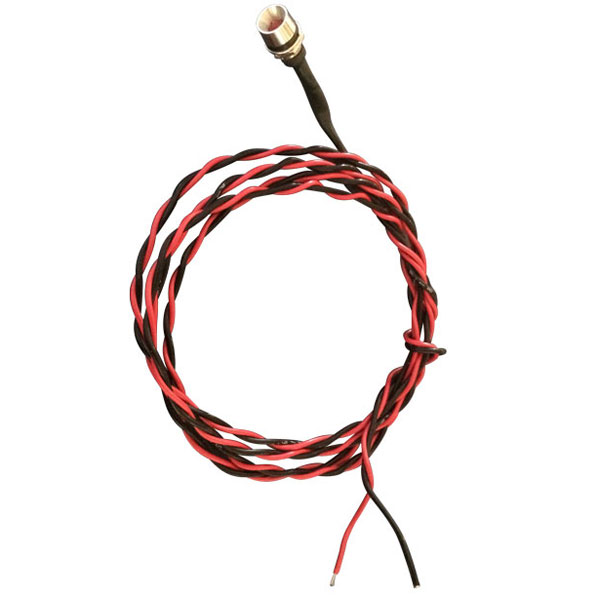
Image for illustration only. It may show a product series rather than the exact product offered.
EarthX LED Fault Light Panel Mount Indicator 12V-5MM
Factory-direct distributor
Roctexo Aerospace is a factory-direct distributor for
EarthX,
the manufacturer of this product. We welcome requests for any quantity of this product,
as well as for other products manufactured by
EarthX.
Part numbers
:
RX1-11-17281
, 5MM-12
, 5MM12
, 11-17281
Unit of Measure:
EA
Orders with purchased items below
100.00 €
incur a small order fee of
10.00 €.
Both amounts exclude VAT. Shipping, other fees and core deposits do not count towards the limit.
Overview
| Easily see if you have a battery fault with this 5mm Red LED light for your EarthX experimental aircraft. The 12V LED has a built in resistor for easy installation and compatibility with a 10-15V electrical system. Details installation directions are located in the EarthX manual but it is very simple. To install, connect red wire to a positive bus connection, connect the black wire to fault monitoring wire (also black) that is located on the EarthX battery. |
Specifications
- Color: Red
- Mounting: Nut and Washer (included)
- Termination style: Wire 20ga- 48″ length
- Voltage: 12V
- Built in resistor: 500 ohm, 1/2 Watt
- Drill bit size: .325 or 5/16″
Installation
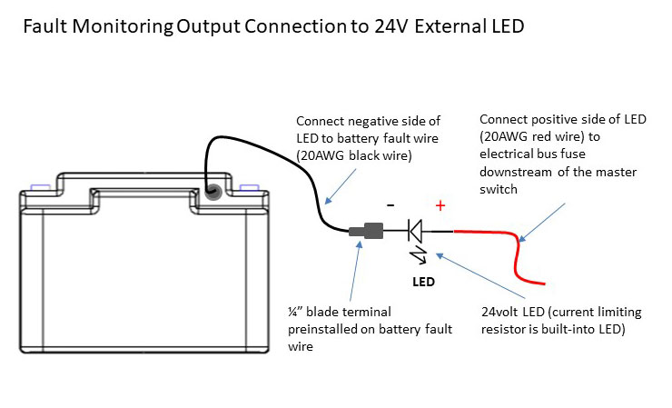
- The positive wire (red wire) of the LED should be connected to the electrical bus (12volt positive), typically to a fuse/breaker downstream of the master switch. The negative of the LED (black wire) should be connected to the fault monitor wire (wire out the side of the battery) of the battery.
- Step 1: install the 12V LED light thru a hole in your control panel.
- Step 2: cut the black wire to length desired for your installation so the LED’s black wire reaches the battery.
- Step 3: use a wire stripper to remove ¼” of the wire insulation so you can attach the “male” spade connector to the black wire. Crimp the male spade connector to black wire.
- Step 4: plug the male spade connector into the end of the pigtail wire from the battery.
- Step 5: connect the red wire to an electrical bus fuse/breaker (.25-1 AMP). May have to untwist wire and cut to length. Most of the time it is most convenient to connect to a fuse on the back side of the panel. If not, it could also be connected directly to the positive terminal of the battery with a ¼” ring lug connector.
Your Dynamic Snippet will be displayed here...
This message is displayed because youy did not provide both a filter and a template to use.
These products might also be of interest
Your Dynamic Snippet will be displayed here... This message is displayed because you did not provided both a filter and a template to use.
Your Dynamic Snippet will be displayed here... This message is displayed because you did not provided both a filter and a template to use.