VHF-5T Nav/COMMAntenna
Part Number(s): 11-04262
Unit of Measure Name:
Units
Internal Reference:
RX1-11-04262
Overview
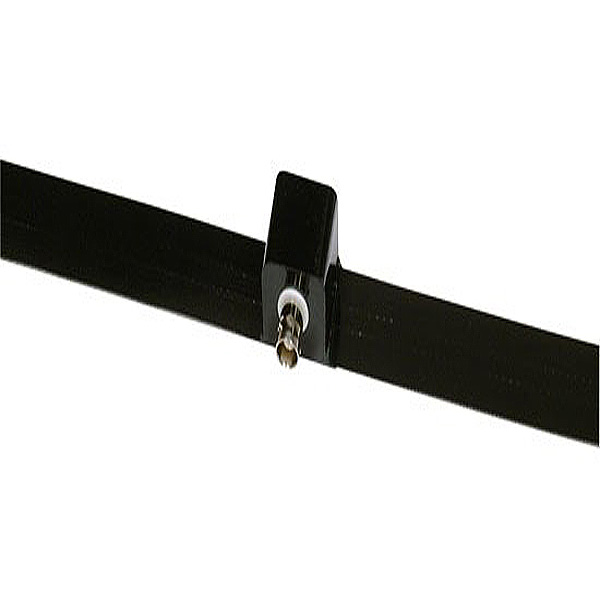
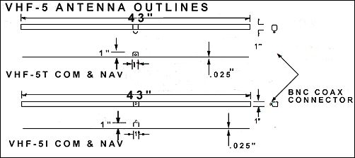
Here is a new series of aircraft antennas specifically designed to be used without a ground plane. This means that composite aircraft and fabric covered aircraft can now have their antennas mounted totally within the structure. These antennas are designed using the latest engineering technology. Laboratory measurements show them to have better electrical characteristics than currently available products. The unanimous reports from pilots who have been using them confirm that they out perform everything now available on the market. One antenna model works for communication, navigation, and for ELT (Three antennas in the aircraft, but all the same design), and this design is tolerant to installation errors. They will work in metal airframes when a plastic or fiberglass wing tip or similar plastic component is available to provide the mounting structure. Model Differences: The VHF antennas, 5T and 5I, differ only in the location of the BNC connection. The 5T is configured to allow the coax cable to be routed flat along the mounting surface of the airframe. This antenna model would be appropriate for a composite aircraft where the antenna would be mounted in the fuselage or fin and the coax would be close to the skin and be attached periodically for strain relief. In either case, the antenna can be used as a retrofit on in service aircraft or in new installations. The 5I series has the BNC connection positioned so that the coax cable would route out and away from the antenna mounting surface. This configuration is offered for antenna installations such as wing tips of fabric aircraft. If the antenna is mounted on the inside of the tip, the coax route is directly inward toward the wing root and the BNC connection is located near the spar to provide support for the cable. Both antennas are identical in their electrical performance. |
Features
- Inside mounting.
- Use w/ composite skins.
- Use with fabric covered airframes.
- Glue or bond to the airframe. Light weight.
- Wide service temperature,
- No ground plane corrosion, Mount anywhere inside, Maximum range with low VSWR.
- Model VHF series designed for comm or nav or ELT (121.5 only)
- Guaranteed against failure for the life of the airframe.
- Adapts to existing airframes or to in process construction.
- Glue or bond to the airframe. Light weight. Wide service temperature, No ground plane corrosion, Mount anywhere inside, Maximum range with low VSWR. Model VHF series designed for comm or nav or ELT. Guaranteed against failure for the life of the airframe. Adapts to existing airframes or to in process construction.
FAQ
Q. What cable length is recommended for the antenna ?
A. Any length can be used. This antenna is impedance matched to 50 ohms to allow you to use any length required.
Q. Can I use it in the plastic or fiberglass wingtip of a metal airplane ?
A. Yes, but the antenna must be as far from the metal wing as possible. We have had limited success with this. Not recommended for the RV series aircraft.
Q. Will the strobes cause interference ?
A. It is possible to couple the strobe audio squeal into the VHF radio. Thishappens when the antenna is close (about a foot) to the strobe.
Q. I thought the com antenna has to be vertical to work.
A. For maximum sensitivity, this is best. The VHF-5 antenna has a higher gainthan others but still when mounted in the horizontal plane the resultantsensitivity is reduced but useable.
Q. Can I mount the antenna on a metal part of my airframe?
A. No ! This antenna works best when separated from all large metal objects.Mounting it on any metal destroys its antenna properties.
Q. Some people have good operation with a ground plane working with their antenna, does this one do the same?
A. No, any ground plane will destroy the effectiveness of this antenna.
Q. My fabric airframe is completed, where is the best location for the antenna?
A. Mount it on a wood brace in the fuselage behind the cockpit. Fasten one end to a location on the lower part of the fuselage frame corner. Then fasten the other end to the opposite or diagonal part of the inside of the upper framecorner. Fasten the antenna to this installed piece of wood.
Q. Should I be careful of the angles at which I mount this wood?
A. No. As long as the antenna is in the same plane as the plane of rotation ofyour propeller, it'll work.
Q. What happens if I mount the antenna on one of my wood stringers on the fuselage?
A. The maximum range will always be off to the sides and the minimum range will be ahead and behind you.
Q. What happens if I mount the antenna on my wood spar in the wing?
A. The maximum range will always be ahead and behind you and the minimum range will off to the sides.
Q. What if the antenna has to be mounted with a bend to fit in the space I want to use?
A. Curving the antenna will fill in those minimum range areas mentioned above at the slight expense of the maximum range.
Q. Can't I have both?
A. No, only a fixed amount of energy can be radiated. If you redirect energy tofill in holes in the pattern you must remove some from one part of theradiation pattern to fill in the other.
Q. Why is it so long compared to others?
A. This is a dipole which is half wave length long and makes it about twice aslong as quarter wave antennas.
Q. Can this be made shorter ?
A. No, it must be used as manufactured. If it is cut to fit, it will be destroyed.
Q. Do I need a 337 ?
A. Perhaps. This is between you, your IA, and the local FAA. It mounts insideand so does not alter the airflow, it attaches with adhesive so no holes oralterations are required for the airframe mount, and it is too light weight toaffect weight and balance.
Q. Will this work on my canopy?
A. Yes, but keep it as far from the metal frame as practical.
Q. Why do I have to keep it away from metal things?
A. Any metal alters the characteristics of the tuning and pattern in unpredictable ways. Each airframe installation is different, so we recommend that you use tape and experiment with locations until you are satisfied with the operation.
Q. Where is a good location in my fiberglass fuselage?
A. Put the com antennas on either side in the tail cone, & if the fuselage isn'ttall enough bend the antennas to resemble the letter"C". If you are using two,stagger them on opposite sides and try to have about 24 inches or more in thestagger.
Q. Why haven't I seen this type of antenna previously?
A. This design has been in operation since 1981 but in response to consumer demand they are now being produced for the non-metal airframe market.
Diagram
These products might also be of interest